Can 30-pin and 40-pin eDP cables be interchanged?
Do not substitute them by contact count. A cable must match the exact source board and panel, both mating connectors, the signal map and the installed route. An adapter that changes physical contact count does not establish electrical compatibility or add a missing interface to the motherboard.
For a replacement, begin with the existing panel model and cable part number. For a new design, begin with the approved panel interface table and source-board schematic. A connector photograph helps identify the housing, but it cannot establish which contact carries panel power or a particular signal.
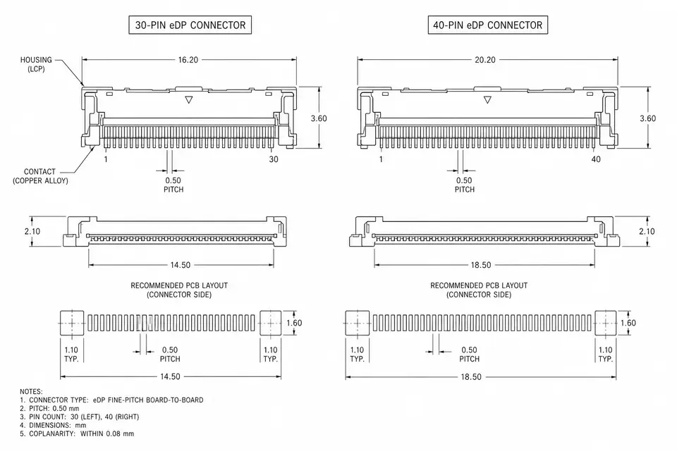
What actually differs between 30-pin and 40-pin?
| Check | 30-pin version | 40-pin version | Evidence to obtain |
|---|---|---|---|
| Physical contact count | 30 contacts | 40 contacts | Exact connector drawing |
| Lane configuration and data rate | Implementation dependent | Implementation dependent | Source and panel interface tables |
| Touch, backlight and power | Use the actual assignment | Use the actual assignment | System schematic and pin map |
| Pitch, latch and contact orientation | Family and part dependent | Family and part dependent | Complete plug/receptacle numbers |
| Resolution and refresh rate | Not defined by contact count | Not defined by contact count | Supported mode and link configuration |
| Replacement compatibility | Requires complete match | Requires complete match | Approved replacement documentation |
The I-PEX CABLINE-VSF family offers 30- and 40-position options. This illustrates a connector choice; it does not assign a universal display mode to either option. VESA's eDP overview describes interface features, rather than a generic cable pin-count rule.
Identify the original screen before ordering
- Record the full panel label, including its suffix, and the equipment model or board revision.
- Find the panel interface specification. Confirm eDP rather than assuming the interface from the housing appearance.
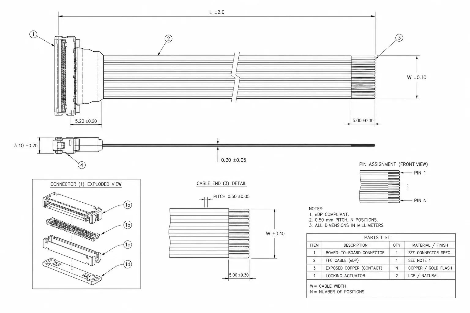
- Record the original cable number and exact connectors at both ends. Check pitch, mating direction, latch and contact orientation.
- Compare the source and panel pin maps, including main-link pairs, AUX, grounds, power, backlight and any implemented sideband functions.
- Verify the operating mode, lane configuration and link rate supported by both endpoints.
- Compare connector location, cable reach, branch exits, hinge path and installed clearance. Release the replacement only after system validation.
Example: the plug fits but the replacement is unsuitable
Consider two candidate cables with the same 40-contact panel connector. One drawing assigns a contact to a supply rail while the other assigns it to a signal. Their housings may fit, but the mismatch must be resolved on the drawing before energizing the equipment. A second candidate may have the correct map yet route its branch across a moving hinge. That is a mechanical review failure even if the display initially works.
These are illustrative design checks, not claims about a particular laptop or a tested EDPcable product. Keep connector fit, electrical mapping and installed operation as separate acceptance decisions.
What to include in an eDP cable RFQ
Provide panel and board documentation, connector part numbers, a point-to-point map, dimensioned route, cable construction requirements, quantity and build stage. Distinguish the drawing's overall length from free cable length between connector reference points. Mark unresolved requirements explicitly so a quotation is not treated as design approval.
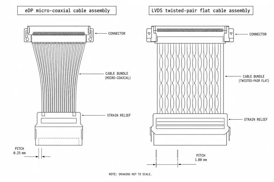
Choose the appropriate 30-pin or 40-pin cable specification after identifying the interfaces. Use eDP cable assemblies for the broader application review and eDP vs LVDS when the signaling interface is uncertain.
Verify mapping and the complete display link
Specify opens, shorts and point-to-point mapping through electrical test planning. A continuity result does not prove high-speed link margin, touch operation or power sequencing. Check the actual source, cable and panel together at the required operating modes, with the approved routing and mechanical conditions.