Tech Journal · #28

ffc-fpc

How to Read a Cable Assembly Drawing

EDPcable Engineering Team2026-07-10
How to Read a Cable Assembly Drawing
ARTICLE · #282026-07-10

Summary

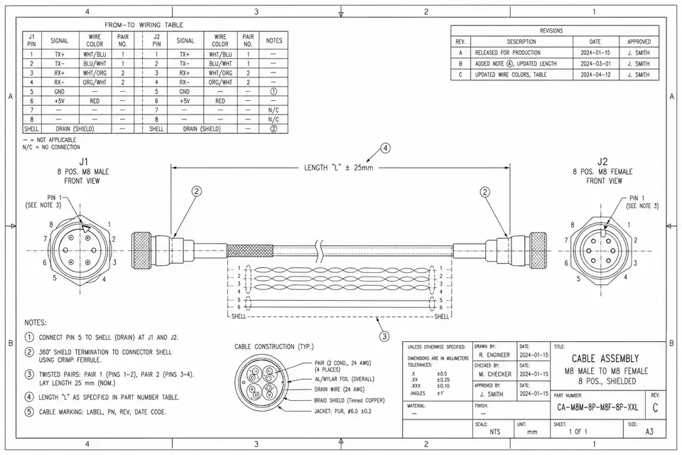
A cable assembly drawing looks like a wall of symbols and little tables, but break it apart and it is just a handful of fixed blocks: a wiring table that tells you which pin connects to which pin, reference designators that say which connector and which orientation, wire callouts that say which wire and what gauge, plus length tolerance, shield and twist, process and inspection notes, and a revision block. Once you can read those blocks, you and your supplier are talking about the same drawing, with far less room for misreading. This article walks a typical drawing in reading order, block by block, with a simplified from-to wiring table example — a practical reading method for buyers and engineers reviewing, revising and signing off drawings. It is written for the buyer.

It Isn't That the Drawing Is Unreadable — You Just Haven't Found the Blocks

The first time a cable assembly drawing lands on your desk, the symbols, abbreviations and little tables can leave you unsure where to even start. But the structure of a cable assembly drawing is actually quite fixed: whoever drew it, the core comes down to a few blocks — a table that says how to wire it up, a few reference designators for the connectors, a wire-specification section, plus length, shield, process and version information. Find the blocks, read them one at a time, and the ambiguity drops away.

The goal of reading a drawing isn't to recognize every last symbol — it's to be able to answer three questions: what is on each end of this cable, how the two ends connect in between, and what counts as a good part. Below we walk a typical drawing in reading order and take those blocks apart one by one.

Start With the Revision Block: Confirm Which Version You Are Looking At

The bottom-right corner of a drawing usually carries a title block and a revision block. Before you read any of the actual content, look at these two: the drawing number, the revision (Rev A / B / C…), the date, and who released it. Revisions are routine on cable assembly projects — swap a connector suffix, nudge the length by a few millimeters, and the version steps up.

Getting in the habit of checking the version first avoids a common trap: discussing new requirements off an old print, or the shop building to the old revision while the customer has already moved to the new one. Confirm the drawing number and revision match on both sides — only then is it worth reading on.

The Wiring Table (From-To): The Core of the Whole Drawing

The wiring table is the heart of a cable assembly drawing — often called a from-to list or a wiring table — and it states, for every conductor, "from which pin, to which pin." Each row is one connection: the source connector and pin, the destination connector and pin, which wire is used, and possibly a net name (signal name) as well.

Three things to watch in a wiring table:

  • The pin-to-pin map. Is it straight-through (1-to-1), crossed over, or jumpered? With the same two connectors, a different wiring scheme builds an entirely different cable.
  • Pinout and signal names. Which pin is power, which is ground, which pins form the differential pairs. Signal names help you judge quickly whether the wiring is right.
  • Any unused / commoned pins. Some pins are left unconnected (NC), or several pins are tied together — the table will call these out explicitly.

A simplified wiring-table example looks roughly like this:

Wire No.FROMTOWireSignal
1J1-1J2-130AWG redVBUS
2J1-2J2-230AWG blackGND
3J1-3J2-432AWG twistedD+
4J1-4J2-532AWG twistedD-
5J1-5NCunused pin

Note: J1 / J2 and the pins and signal names in this table are illustrative only — always follow your actual drawing.

Read this table and you know exactly how the cable is wired — and it is also the block you should review line by line with your supplier.

Connector References and Orientation: Which Interface, Facing Which Way

The J1 and J2 in the wiring table are the connectors' reference designators; for what each connector actually is, look at the connector list (BOM / parts list) on the drawing or the leader callouts. Each designator gets its own row: full part number, brand series, pin count, and mating end.

Beyond "what it is," look at "which way it faces." A cable assembly drawing usually depicts the connector outline and the wire exit direction, marking:

  • The position of pin 1. A connector typically has a triangle mark, a notch or a "1," and the drawing calls out the matching location — it sets which end you count the pinout from.
  • Wire exit direction / latch orientation. Which face the wire exits from, and whether the latch faces up or down, directly affects whether the part fits the device and whether it mates and unmates smoothly.

Orientation looks like a small detail, but it is where assembly problems most often show up. Right part number, right pinout — but the wire exits the wrong way, and the part still won't go in.

Wire and Gauge Callouts: Which Wire to Use

The "wire" column of the wiring table, or a separate wire-specification area on the drawing, says which wire each conductor uses. Common callouts include gauge (AWG — the larger the number, the thinner the wire), conductor count, insulation material, color or color stripe, and whether it is UL-recognized wire.

A few easy-to-miss points:

  • Gauge vs. current / voltage drop. Gauge isn't only about thickness; it governs how much current the wire can carry and how much voltage it drops. Where the drawing specifies a gauge, don't casually swap in something thinner.
  • Color / color code. Colors are used to tell conductors apart during assembly — get the color code wrong and you wire it wrong.
  • Special wire. Coax, twisted pair and shielded wire are marked with dedicated symbols or notes — more on those in the next block.

Shield, Twist and Process / Inspection Notes

These categories of callout set the cable's electrical performance and workmanship requirements, and they are scattered across the drawing notes and the wiring table:

  • Shield. Whether the cable is shielded and how the shield is terminated (where the ground point is, whether it is a 360° circumferential bond, whether a drain wire is provided). High-speed cables and those with high noise-immunity requirements especially need a close read here.
  • Twist / lay length. Whether differential pairs must be twisted, and the lay-length range. Pairs that appear together in the wiring table with +/- signal names are almost always differential pairs.
  • Impedance / test requirements. Target impedance (such as 90 Ω / 100 Ω), and whether continuity testing, hipot testing or signal-integrity testing is required.
  • Process and inspection. Termination method (crimp / solder), which acceptance standard the work follows, whether a first-article inspection is required, and lacing and sleeving requirements.

The notes column (usually numbered 1, 2, 3 in a corner) often hides the most critical process requirements — don't read only the graphics and skip the text.

Read the Whole Drawing, Then Go Back and Cross-Check

Once you've read it block by block, go back and do a cross-check: every connector reference in the wiring table has a matching part number in the BOM; every gauge a wire uses is defined in the wire-specification area; every test and process the notes mention has a landing point on the drawing. When all three line up, the drawing is truly read.

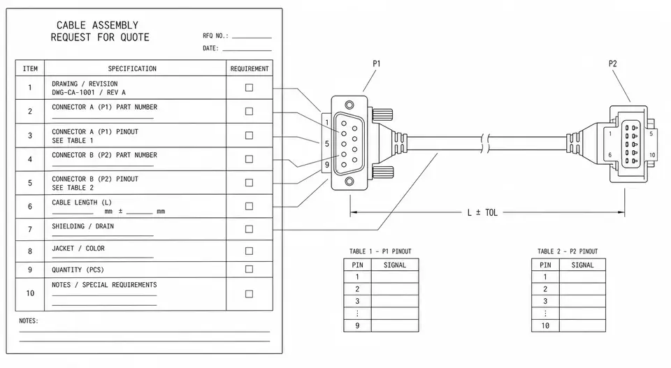
If the drawing you're holding is missing the wiring table, has an incomplete pinout, or simply hasn't been formally issued yet, that is a different matter — what's needed then is an RFQ that states the requirements clearly. Reading a drawing and writing requirements are a pair: How to Write a Cable Assembly RFQ That Gets the Quote Right the First Time covers how to lay out the requirements in full before the drawing exists, and complements this article directly.

If you have a complete drawing and want to build the cable, or want a second set of eyes to review the drawing for manufacturability, go straight to the custom cable assemblies inquiry — send the drawing over and we'll go through it together.

FAQ04

Frequently asked questions

  • Which block do you read first?

    Start with the revision block to confirm you have the right version, then read the wiring table (from-to). The wiring table tells you which pin each conductor runs from and to — it is the single most important information on the sheet, and everything else (connectors, length, process) is built around it. If the version is wrong, even the most careful reading may be of an outdated drawing.

  • The drawing has no pinout, just two connectors drawn — can the shop build it as is?

    Not recommended. With the same two connectors, a straight-through wiring scheme and a crossover scheme produce completely different parts; without a pin-to-pin map, the shop has to guess or come back and ask. A drawing with no wiring table usually needs one added — confirm the pinout before release to production.

  • No length tolerance is given — what does the shop build to?

    When no tolerance is stated, a shop generally falls back to its internal default band, but that default may not match your assembly needs. Length directly determines whether the part fits the device, so it is best to call out the overall length and tolerance on the drawing — especially when the wire has to be routed and dressed to shape or fit into a fixed space.

  • The drawing and the physical sample disagree — which one governs?

    First confirm the drawing is the latest version. If it is current and they still disagree, the drawing usually governs and the sample's differences get flagged, because the drawing is the technical reference both sides have agreed to; but list every point of difference and review them together, so you don't end up with one side revising the drawing while the other keeps building to the old sample.

Last updated: 2026-07-10
SEC · 03Related applications

Related applications

SEC · 02Related Articles

Related Articles

How to Write a Cable Assembly RFQ That Gets Quoted Right the First Time
POST · 012026-07-02

EDPcable Engineering Team

How to Write a Cable Assembly RFQ That Gets Quoted Right the First Time

When a cable assembly quote drags through round after round, the supplier usually isn't slow — the RFQ is just missing the few details that let anyone scope the build. An RFQ that can be quoted accurately on the first pass needs to spell out a handful of dimensions: a drawing or an old sample, full connector part numbers and pinout, length and routing, shielding, impedance and test requirements, the operating environment, quantities by phase, and any certification or documentation. This article walks through what each one should contain, shows how a few common gaps trigger predictable follow-up questions, gives you a copy-and-paste input checklist, and explains how to feed information in stages when you don't have it all yet — so the other side can still quote something. It's a practical guide written for the buyer.

Read More: How to Write a Cable Assembly RFQ That Gets Quoted Right the First Time
What Drives a Cable Assembly's MOQ and Lead Time — and How to Shorten Both
POST · 022026-07-08

EDPcable Engineering Team

What Drives a Cable Assembly's MOQ and Lead Time — and How to Shorten Both

A cable assembly's MOQ is rarely a number the factory invents on the spot — it is pushed up, layer by layer, by the connector's minimum packaging, material availability, tooling and fixture amortization, and the cost of a line changeover. Lead time is four stretches of time strung together: prototyping, material procurement, test and verification, and logistics — and material procurement is usually the longest and the hardest to compress. This article unpacks what drives MOQ and lead time separately, explains why the prototype cadence differs from the production cadence, and offers four moves that actually shorten both: lean on standard connectors, pre-stock materials, freeze the revision early, and deliver in batches when capacity allows.

Read More: What Drives a Cable Assembly's MOQ and Lead Time — and How to Shorten Both