Why These Three Connectors Keep Ending Up Side by Side
On high-density display and micro-coaxial projects, connector selection almost always runs through the same three Japanese makers: I-PEX, Hirose and JAE (Japan Aviation Electronics). All three have spent years deep in fine-pitch internal interconnect, and each spreads its series wide — CABLINE, MHF, DF and FI prefixes landing in one BOM together, easy to lose track of.
Putting them side by side isn't about crowning a winner. The three lean toward different signal types and different interface forms; far more often they complement each other rather than substitute. What this article builds is an interface map: first get clear on which kinds of interface each house is strong in, then pin down what "mating-compatible" really means — so you take fewer detours between drawing and quote.
EDPcable provides custom cable assembly manufacturing built to be compatible with these interface systems; every brand name below is used only to identify the mating interface direction.
Where Each House Is Strong
All three product lines run long, so here we grab only the trunk to give you a first layer of judgment.
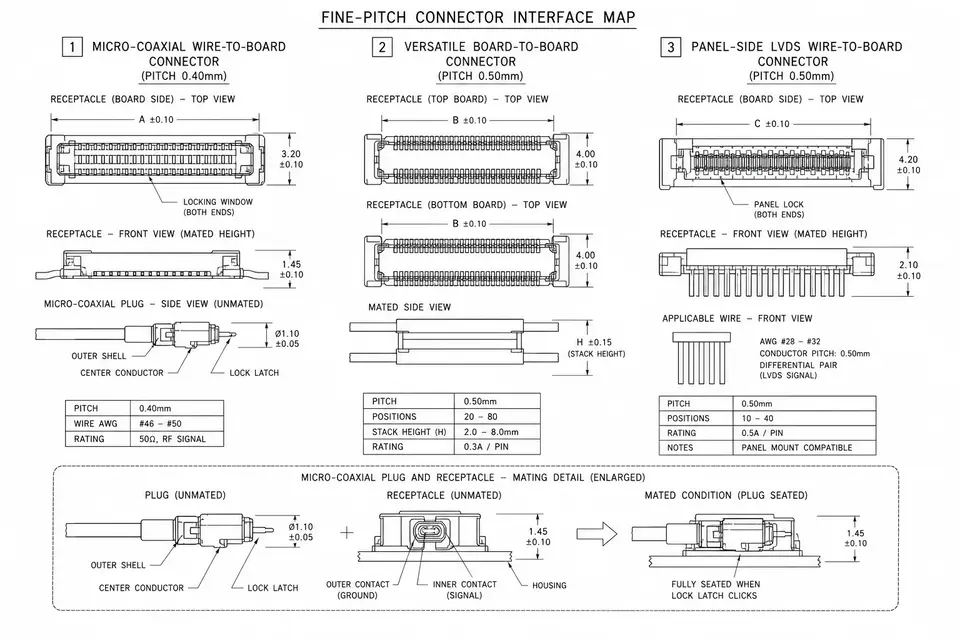
I-PEX is highly recognizable in micro-coaxial and miniature RF. On the wire-to-board side sits the CABLINE family — common in laptops, tablets and automotive internal high-speed display interconnect, going the micro-coax-plus-high-density route; on the RF side, the MHF family is a frequent choice for the miniature coaxial connections in phones and module antennas. On high-speed differential display harnesses, the CABLINE direction turns up often.
Hirose runs the DF series as a sprawling family, covering everything from board-to-board and wire-to-board to micro-coaxial, with a wide spread of pitch and pin count — a regular in plenty of consumer electronics and industrial equipment. On the RF side, U.FL also comes from Hirose, one of the earliest series to make the miniature coaxial interface an industry-wide reference point.
JAE (Japan Aviation Electronics) shows up often on the LVDS and display interconnect side, with the FI series as its representative — FI-X and the like are common for panel-side LVDS interfaces. When display signals need to travel from the mainboard to the panel, the FI series is frequently among the connector options.
These three reads are a coarse sense of direction, not a boundary. Each house subdivides its series further by pitch, shielding and form factor, and once it comes down to a specific part number, you still go back to the original manufacturer's catalog to confirm.
One Table, Side by Side
The table below lays the three houses' trunk series together across a few engineering dimensions, so you can place a candidate quickly during selection. The cells give directional ranges; the exact pitch and suffix shift with how each series subdivides, so the manufacturer's catalog and your own drawing remain the authority.
| Dimension | I-PEX | Hirose | JAE (Japan Aviation Electronics) |
|---|---|---|---|
| Representative series | CABLINE, MHF | DF series, U.FL | FI series |
| Main interface form | Micro-coaxial wire-to-board, miniature RF coaxial | Board-to-board / wire-to-board / micro-coaxial / RF | Wire-to-board (mainly panel-side LVDS) |
| Typical pitch range | Fine-pitch band (e.g. the 0.4mm-class direction) | Wide spread, from coarser to fine pitch | Common display-interface pitch band |
| Signal emphasis | High-speed differential display, RF | General-purpose, covers many signal types | LVDS / display signals |
| Typical applications | Laptop / tablet / automotive internal display, module antennas | Consumer electronics, industrial equipment, RF antennas | Panel-side LVDS, display modules |
| RF coaxial representative | MHF | U.FL | — (display interconnect focused) |
The table is for narrowing the field fast; final selection still comes down to whether three things line up — the signal type you're carrying, the pitch, and the pin count — not to which house has the bigger name.
What "Mating-Compatible / Equivalent Direction" Actually Means
This is the single most misread point when the three sit together, and it earns its own section.
When the field calls two connectors "mating-compatible" or "equivalent," it means their RF or interface geometry lines up in the mating direction — the plug seats into the matching receptacle — not that two part numbers can be swapped freely. The textbook case is U.FL and MHF: U.FL is Hirose's miniature RF coaxial series, MHF is the corresponding series on the I-PEX-compatible side, and in many scenarios the two RF plugs mating with each other is accepted industry knowledge.
But "mating-compatible" has limits:
- It's about interface geometry and the mating definition, not how alike the part numbers look. Similar names don't guarantee they mate, and different names may still sit in the same mating direction.
- Suffix and frequency band can change the answer. Within one series, different suffixes can differ in frequency range, retention force, and whether they latch; whether two specific parts interchange has to be checked in the original manufacturer's catalog.
- Compatibility is interface-direction compatibility, not a brand endorsement. Saying a harness is "compatible with the MHF interface" means it's built to mate with that interface — it implies no authorization or partnership with the brand owner whatsoever.
So when a drawing carries a note like "U.FL/MHF intermateable," read it as "the interface mating direction matches" — and for the specific part number, still defer to both manufacturers' catalogs.
How to Use This Map for Selection
Putting the comparison into actual practice, the order runs roughly like this:
- Fix the signal type first. High-speed differential display signals point toward the I-PEX CABLINE micro-coax wire-to-board direction; pure RF antenna signals point toward the MHF / U.FL miniature coaxial direction; LVDS display signals make the JAE FI series a common starting point; general board-to-board or wire-to-board is broadly covered by the Hirose DF series.
- Then match pitch and pin count. Once the signal type is set, narrow to a specific series within the matching family by the pitch and pin count on the drawing.
- Last, verify the mating direction. Different brands on each end of one harness is perfectly normal; what matters is that each end mates correctly on its own — confirm this step item by item against the original manufacturer's catalog and the customer drawing.
The interface map helps you locate a direction fast, but the part number is settled by the two authorities that count: the drawing and the original manufacturer's catalog. For how to take a connector part number apart, see How to Read Connector Part Numbers; for why pitch is such a pivotal parameter, see What Is Connector Pitch.
Trademark & Brand Notice
I-PEX® is a registered trademark of I-PEX Inc.; CABLINE and MHF are its connector product series identifiers. JAE™ is a trademark of Japan Aviation Electronics Industry, Ltd.; the FI series is its connector product series identifier. Hirose™ is a trademark of Hirose Electric Co., Ltd.; the DF series and U.FL are its connector product series identifiers. These names are used solely to identify the mating interface direction. The products referenced in this article are cable assemblies independently designed and manufactured by EDPcable, which is not affiliated with, authorized by, distributed by, or otherwise related to the respective owners above. When a customer drawing or BOM has already specified a given interface system, we provide custom cable assembly manufacturing built to be compatible with that interface; final delivery is governed by the drawings, samples, and engineering definitions confirmed by both parties.