When a Quote Drags, the RFQ Is Usually the Reason
A lot of custom cable assembly inquiries stop at "we need a batch of 30-pin cables, please send a quote." That one line tells the other side roughly what you want, but it isn't enough to price. What follows is a string of follow-ups: which connector? how long? shielded or not? how many? A few email rounds later, a week is gone and the build still isn't defined.
The problem isn't that anyone is slow to reply — it's that the first RFQ didn't deliver, in one shot, the information needed to scope the job. A cable assembly is configured to order: connector, wire, termination and test each move both the price and the lead time. The more specific the RFQ, the more accurately the other side can quote on the first pass, and the fewer rounds it takes. Below is what a complete RFQ should carry, followed by the follow-ups a few common gaps tend to trigger.
What a Complete RFQ Should Include
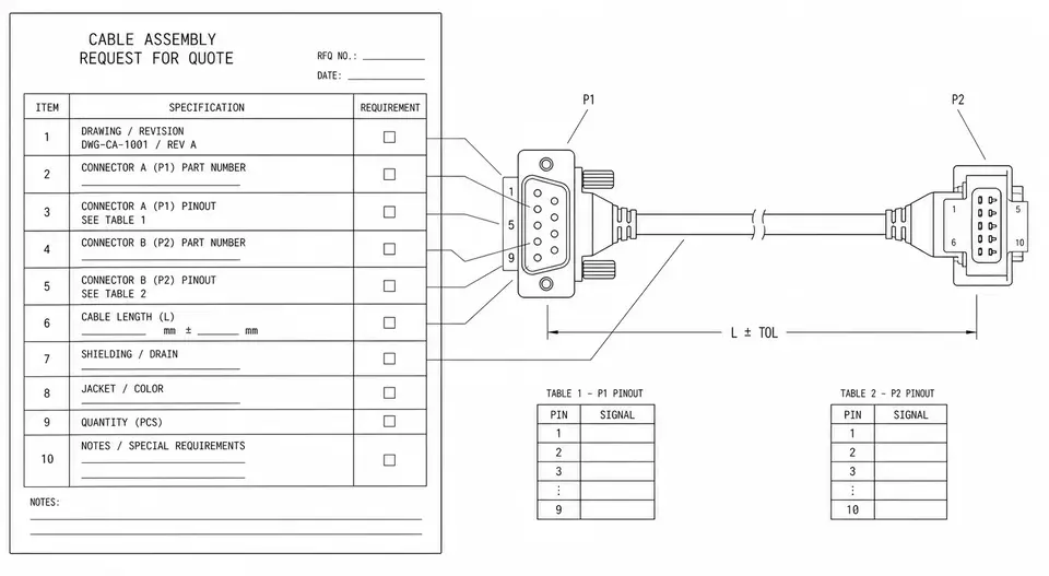
Think of it as a checklist for stating the requirement once. You don't have to fill every line, but each blank is a possible extra round. Broken out by dimension, it comes down to a few blocks:
- A drawing or an old sample. An assembly drawing is ideal; failing that, the physical reference part or clear photos can still pin down both interfaces and the rough structure. This is the single biggest round-saver.
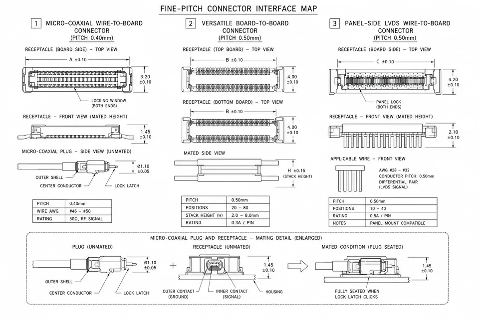
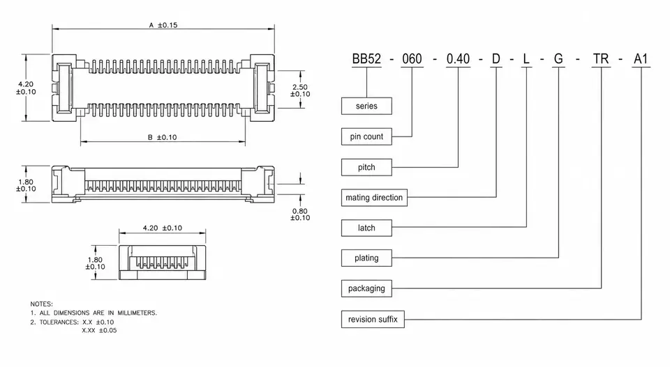
- Full connector part numbers + pin definition / pinout. Both ends, with the suffix — not just the series name — plus a pin-to-pin definition that says which pin goes where. For how the codes read and why the suffix matters, see "How to Read Connector Part Numbers."
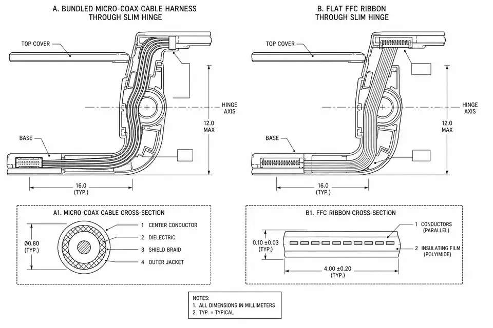
- Length and routing / bend. Give the overall finished length and tolerance; if there are branches, a set bend, or it has to fit a specific space, include the routing and the minimum bend radius.
- Shielding / impedance / test requirements. Whether it needs shielding, single-ended or differential, the target impedance (such as 90Ω / 100Ω), whether continuity and hipot testing are required, and any signal-integrity targets. For high-speed assemblies, this block drives the wire selection directly.
- Operating environment. Temperature range, whether there's continuous vibration or repeated flexing, and whether it contacts fluids or needs cleaning and disinfection. The environment decides the jacket and the termination process.
- Quantities and phases. How many at sample, pilot and production, and roughly when. Pricing tiers with volume, so the phases have to be clear before the matching prices can come back in one go.
- Certification or documentation requirements. Which compliance points apply (such as RoHS / REACH), whether UL-recognized wire is needed, whether a medical build involves the relevant documentation, and whether you need a first-article inspection report or material certificates.
Skip These, and You Usually Buy Another Round
You don't need the whole list from memory, but a few items almost always trigger a follow-up if they're missing, so they're worth getting in first:
- A connector series name with no full part number or mating end. Within one series, latched versus unlatched and thicker versus thinner plating can differ; the other side can't confirm which one to mate to and has to ask back — and at the sample stage it can easily fail to fit the equipment.
- A length with no routing or environment. The same 200mm cable run free versus shaped to fit a tight space is two builds and two prices. Environment is the same — room-temperature static versus continuous vibration calls for entirely different wire and termination, and leaving it out means re-estimating.
- No quantity or phase. Quote a single quantity and the other side will tool and test for it by default; add volume later at production and the tooling and unit price may both need recalculating. Flagging the staged estimates up front avoids re-pricing when you scale.
What these share: without them, a quote can only rest on assumptions — and assumptions come back for confirmation sooner or later, which is one more round.
A Copy-and-Paste Input Checklist
Fill in the table below and you've covered most of what it takes to quote accurately on the first pass. Where you can't, write "TBD" or give a range — still better than a blank, since it lets the other side judge which tier to quote first.
| Dimension | What to provide | If you don't have it |
|---|---|---|
| Structure | Assembly drawing / reference part / photo | Describe both interfaces + rough structure in words |
| Connectors (both ends) | Full part number (with suffix) + mating end | Series name + photo of the part or the board header |
| Pinout | Pin-to-pin definition | Mark the key pins (power / ground / differential pairs) |
| Length | Overall finished length + tolerance | Give a length range |
| Routing / bend | Branches, set bend, minimum bend radius | Describe the space or equipment it fits into |
| Shielding / impedance | Shielded or not, target impedance, diff/single-ended | Describe the signal type and rate |
| Test | Continuity, hipot, signal-integrity targets | Describe the matching application |
| Environment | Temperature, vibration, flexing, fluids / cleaning | Describe how the equipment is used |
| Quantity / phase | Sample / pilot / production quantities and timing | Give an order-of-magnitude range |
| Certification / docs | RoHS/REACH, UL wire, inspection reports, etc. | Describe the end market and industry |
When You Don't Have Everything, Feed It in Stages
You don't have to wait until every document is in hand before sending an RFQ. Early in a project the drawing often isn't out and the production quantity isn't set yet — that's normal. The smoother approach is to work in two steps.
First, send what's already locked — connectors for both ends, an approximate length, the expected phases and quantities — and attach the reference part or photos. That's enough for the other side to give a directional quote and a list of things to clarify, and enough for you to judge whether this supplier is the right fit.
Second, before the sample or pilot run, fill in the drawing, the full pinout, and the test and certification details to lock the price and the tooling. Separating "ask for direction first, settle the details later" is actually faster than waiting to send it all at once — and it surfaces, early, the parts of the requirement that weren't fully thought through.
If what you have is a complete custom project, from scoping the requirement through to prototyping, go straight to the custom cable assembly inquiry and attach the checklist above — it cuts out most of the back-and-forth.