REF · edp-cabline-30pin-display-cable
Low-Profile CABLINE 30Pin eDP Display Cable for Ultra-Thin Projects
Contact for Quote
REF · edp-cabline-30pin-display-cable
SPEC SHEETeDP Cable Assemblies
SEC · 01
Product Overview
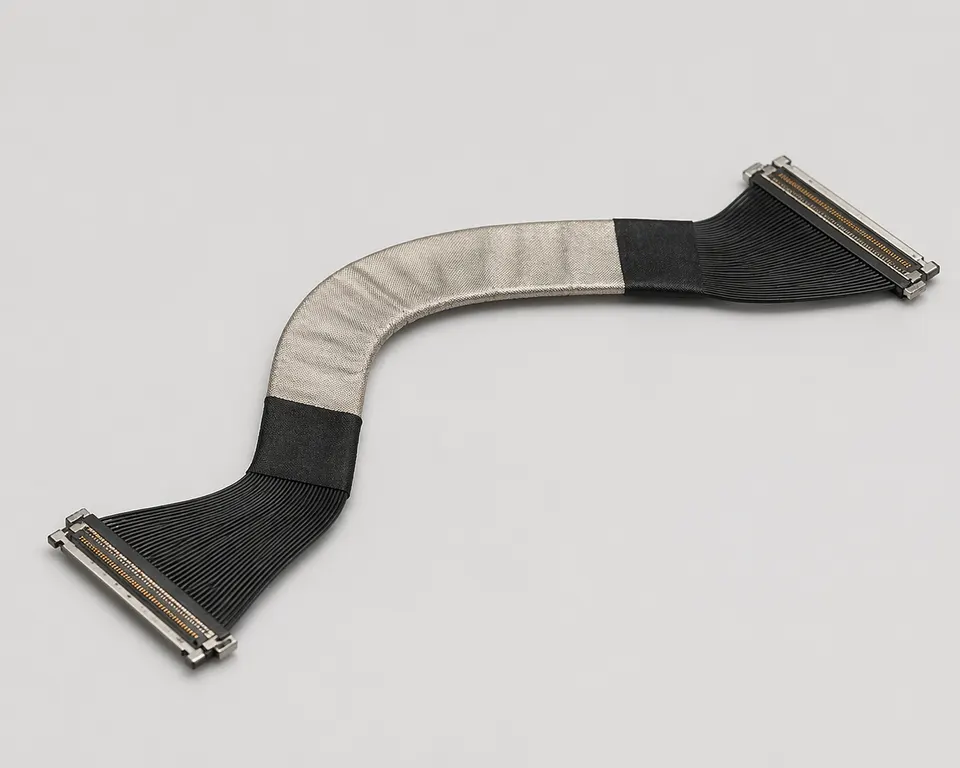
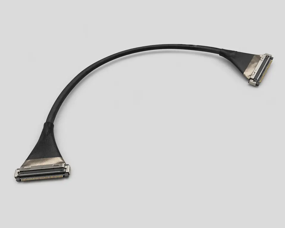
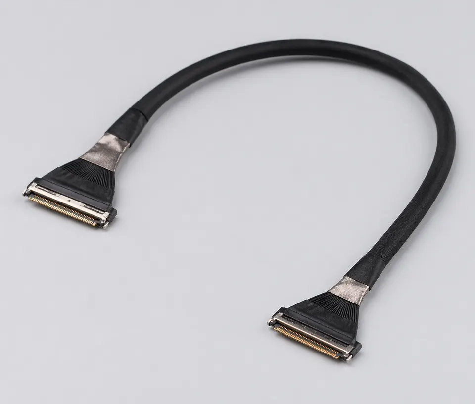
A low-profile CABLINE display cable is released against exact receptacle and plug part numbers, because similar 30-position shells can differ in pitch, mating height and cable support. The selected micro-coax construction must also fit the available bezel or hinge space.
Application Scenarios
- Mainboard-to-panel display links in notebooks, tablets and compact displays
- Industrial HMI, embedded display and remote panel programs
- Thin-bezel or hinge-routing designs with restricted cable space
- Prototype and production builds requiring controlled impedance and repeatable assembly
Custom Options
- Pin count, connector series, exit direction and cable length can be customized
- Micro-coax, twisted-pair or hybrid structures can be selected per signal requirement
- PI stiffeners, EMI tape, foam, grounding tabs and adhesive fixing can be added
- Sample validation can be aligned with the actual LCD panel, mainboard connector and hinge path
RFQ Inputs & Material Requirements
Provide both original-maker connector numbers, panel model and pin map, mating-height and keep-out limits, exit direction, cable length, shield termination, installed bend path and eDP link-validation conditions.
SEC · 02
Technical Specifications
SPECIFICATIONS · 10 ROWS
- 01Connector Type
- 30Pin low-profile CABLINE style eDP connector
- 02Signal Type
- eDP differential display signal
- 03Cable Structure
- micro-coax
- 04Differential-Impedance Acceptance
- Target, tolerance, finished length, fixtures and method defined by the panel or link validation plan
- 05Structure Focus
- low connector height / thin structure / restricted space assembly
- 06Finished Length
- Controlled drawing dimension and tolerance
- 07Shielding Method
- aluminum foil shield + local EMI tape
- 08Fixing Structure
- PI stiffener / foam / adhesive optional
- 09Environmental Exposure
- Limits taken from the approved cable, connector and material BOM for the installed environment
- 10Inspection Items
- continuity / wire order / appearance / assembly confirmation
01
02
03
04
05
06
07
08
09
10
SEC · R · Related Products