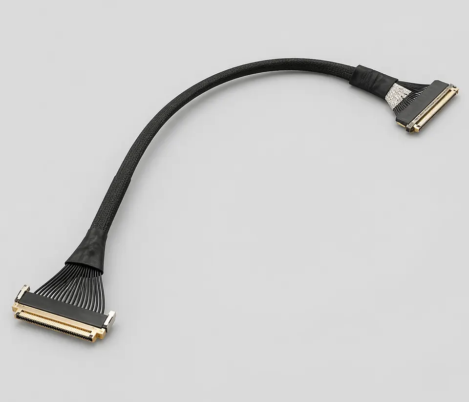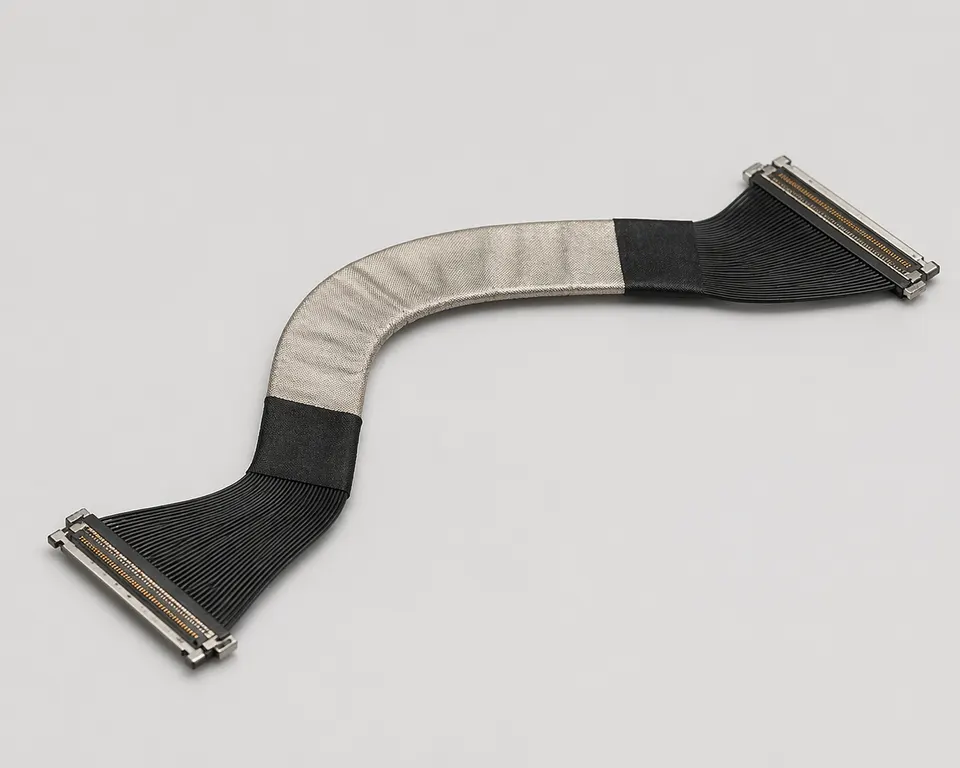
REF · edp-30pin-lcd-cable-assembly
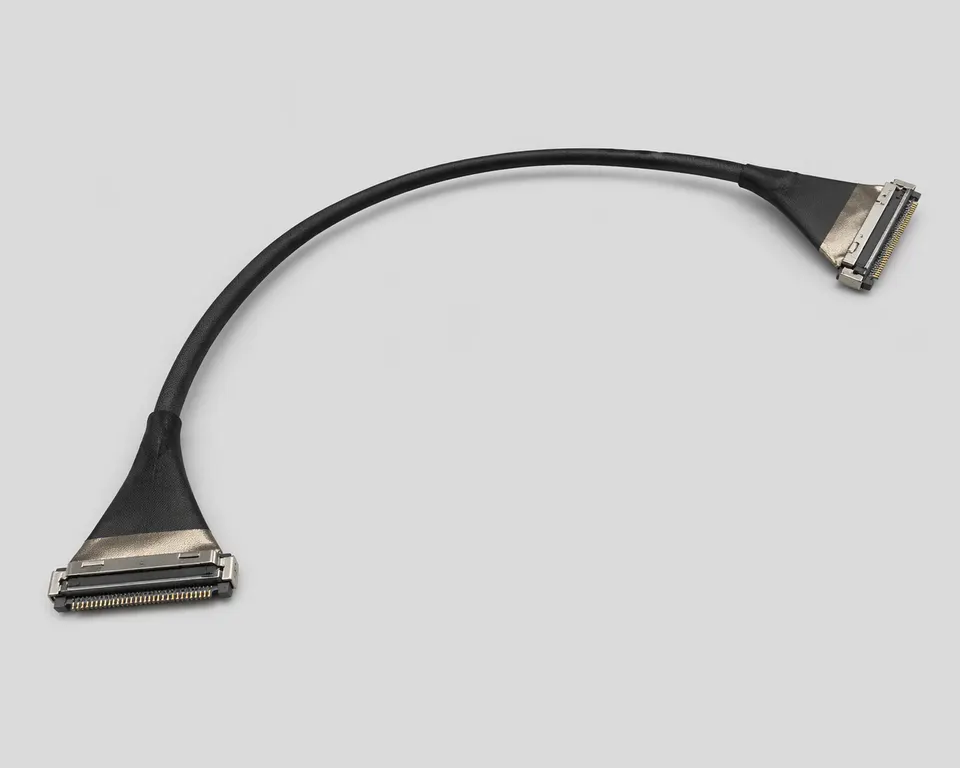
REF · edp-30pin-lcd-cable-assembly
SPEC SHEETeDP Cable Assemblies
SEC · 01
Product Overview
This 30-position eDP cable connects one named panel to one named mainboard interface. Connector pitch, lane assignment, AUX and power pins, shield termination and hinge routing come from the two component drawings and panel pin map.
Application Scenarios
- Mainboard-to-panel display links in notebooks, tablets and compact displays
- Industrial HMI, embedded display and remote panel programs
- Thin-bezel or hinge-routing designs with restricted cable space
- Prototype and production builds requiring controlled impedance and repeatable assembly
Custom Options
- Pin count, connector series, exit direction and cable length can be customized
- Micro-coax, twisted-pair or hybrid structures can be selected per signal requirement
- PI stiffeners, EMI tape, foam, grounding tabs and adhesive fixing can be added
- Sample validation can be aligned with the actual LCD panel, mainboard connector and hinge path
RFQ Inputs & Material Requirements
Provide the panel model, complete connectors at both ends, pin assignment, eDP lane count and link rate, finished length, hinge envelope, ground and shield plan, and the continuity and link-validation method.
SEC · 02
Technical Specifications
SPECIFICATIONS · 11 ROWS
- 01Connector Type
- 30Pin eDP fine-pitch connector
- 02Signal Type
- eDP differential display signal
- 03Cable Structure
- micro-coax / high-speed hybrid structure
- 04Differential-Impedance Acceptance
- Target, tolerance, finished length, fixtures and method defined by the panel or link validation plan
- 05Connector Pitch
- Exact value from the selected connector mating drawings
- 06Finished Length
- Controlled drawing dimension and tolerance
- 07Shielding Method
- aluminum foil shield + ground drain wire
- 08Fixing Options
- adhesive / PI stiffener / EMI Tape / foam
- 09Installed Bend Limit
- Minimum radius and method defined by the route drawing and validation plan
- 10Environmental Exposure
- Limits taken from the approved cable, connector and material BOM for the installed environment
- 11Test Items
- continuity / open / short / appearance / assembly confirmation
01
02
03
04
05
06
07
08
09
10
11
SEC · R · Related Products