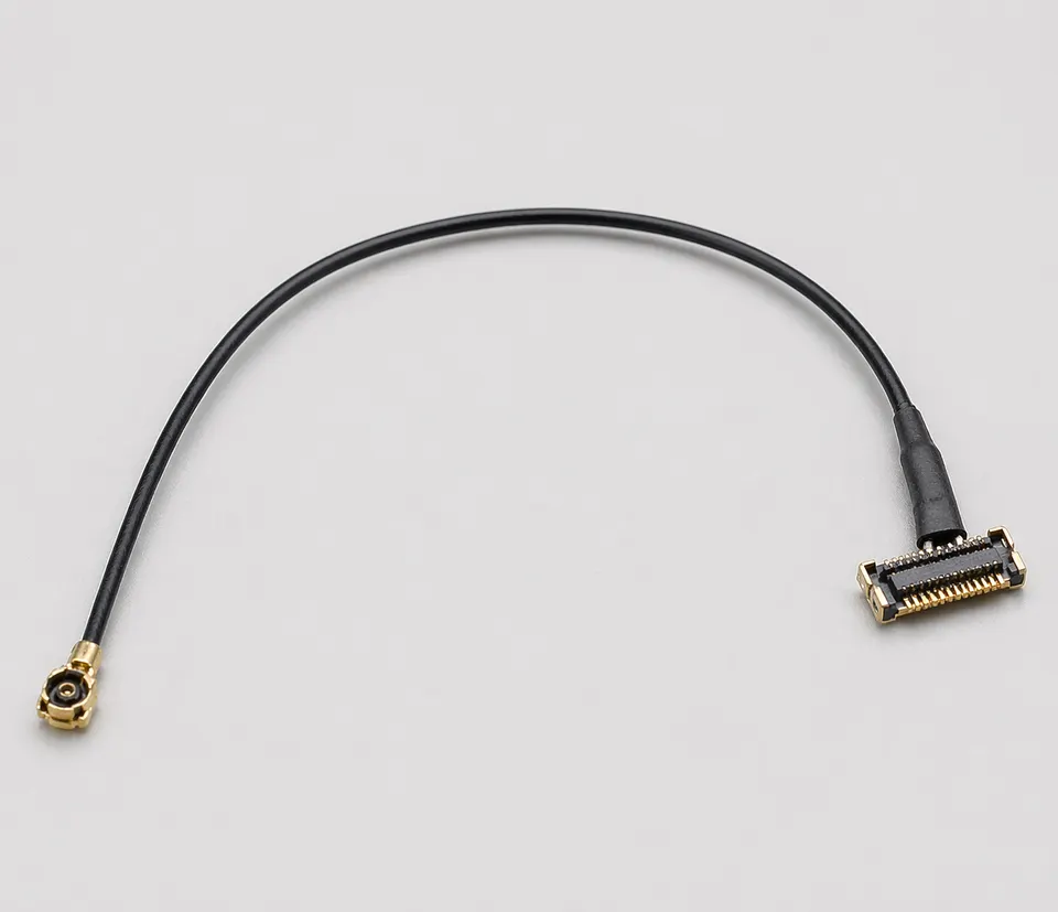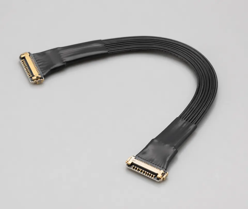
REF · mca-lte-mhf4-antenna-cable
LTE Antenna Micro-Coax Cable with MHF4 Board-Side Feed
Contact for Quote
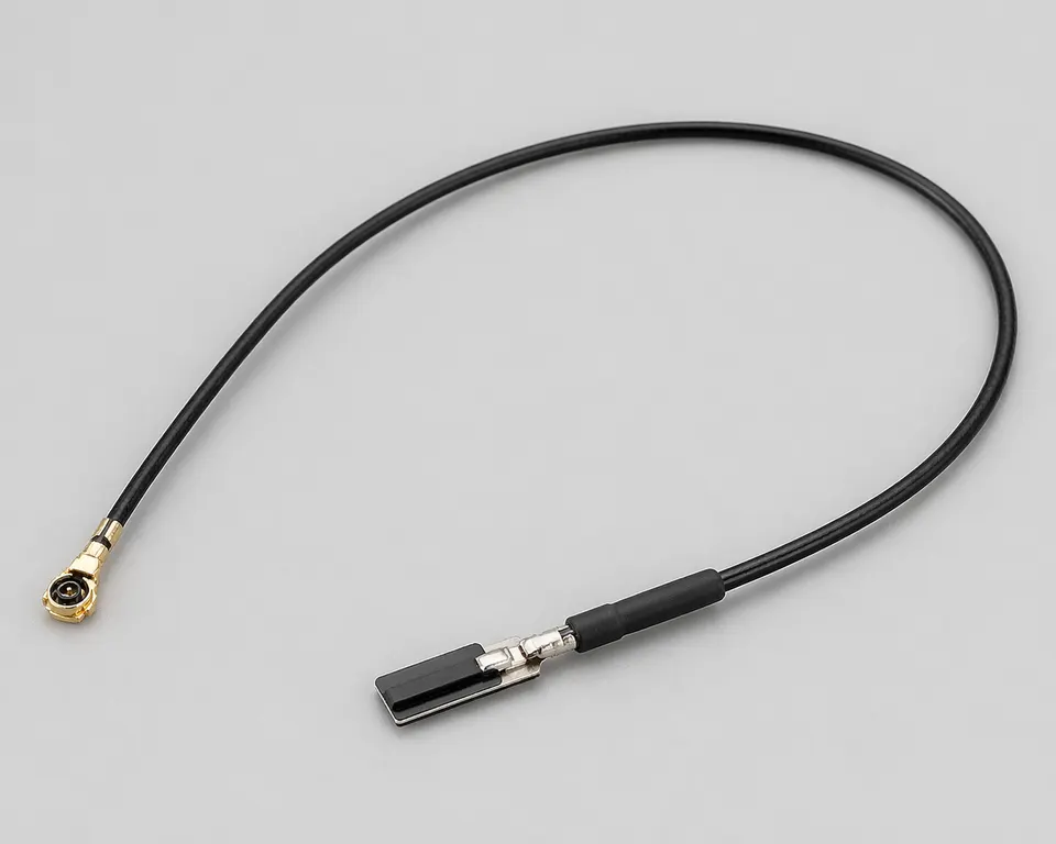
REF · mca-lte-mhf4-antenna-cable
SPEC SHEETMicro-Coaxial Cable Assemblies
SEC · 01
Product Overview
This cellular feed uses a specifically identified MHF4 board-side mating pair; U.FL and other miniature RF families are not substitutes. The antenna end, cable source, cellular bands and installed route complete the RF definition.
Application Scenarios
- Antenna feed links for WiFi, LTE, GPS/GNSS and general RF modules
- Camera modules, UAV/FPV systems and compact wireless devices
- Board-to-antenna transitions using U.FL, MHF4, MMCX, SMA or similar interfaces
- RF builds requiring stable impedance, bend control and reliable miniature termination
Custom Options
- Cable diameter, connector combination, length and exit direction can be customized
- 0.81mm, 1.13mm, RG-178 and other coax options can be reviewed per frequency and routing need
- Insertion-loss reference, continuity and termination inspection can be included
- Samples can be matched to module layout, antenna position and enclosure routing
RFQ Inputs & Material Requirements
Provide the module model, exact MHF4 receptacle and plug, antenna termination, cellular and auxiliary bands, cable part number, finished length, board keep-out, enclosure route and frequency-specific loss or return-loss limits.
SEC · 02
Technical Specifications
SPECIFICATIONS · 10 ROWS
- 01Product Type
- Cellular antenna feed cable built to an approved module and antenna definition
- 02Board-Side Interface
- Exact MHF4 plug and module-side receptacle part numbers
- 03Antenna-End Interface
- Exact antenna connector or termination from the controlled drawing
- 04Cable Construction
- Cable manufacturer and part number supported by both terminations and the installed route
- 05Nominal System Impedance
- Project target tied to the selected RF chain
- 06Target RF Bands
- Customer cellular band plan, including any GNSS or diversity paths
- 07Finished Length
- Controlled drawing dimension and tolerance
- 08Shield Termination
- Connector and grounding details from the approved drawing
- 09Environmental Exposure
- Project-defined temperature, vibration and enclosure conditions
- 10Inspection Items
- Continuity, termination inspection and agreed band-specific RF acceptance
01
02
03
04
05
06
07
08
09
10
Applications
PILLARSee how the Micro-Coaxial Cable Assemblies family fits real projects.
Open Application PageSEC · R · Related Products