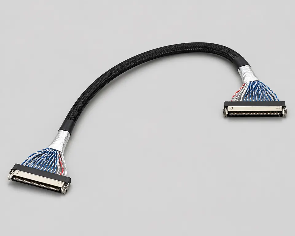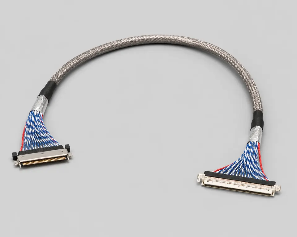
REF · lvds-40pin-dual-channel-cable
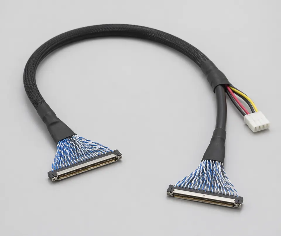
REF · lvds-40pin-dual-channel-cable
SPEC SHEETLVDS Cable Assemblies
SEC · 01
Product Overview
This 40-position harness carries dual-channel LVDS and may include a separate backlight branch. Pair order, branch current, connector orientation and the return path must match the panel datasheet and backlight interface.
Application Scenarios
- Industrial display panels, medical monitors and embedded display modules
- Board-to-panel LVDS links with defined signal, power and control circuits
- Display harnesses that require shielding, grounding or backlight branches
- OEM projects requiring stable routing, inspection and repeatable production
Custom Options
- Pin count, connector family, length and branch layout can be customized
- Shielded twisted-pair, hybrid power/signal and backlight branch structures are available
- Grounding tabs, foam, adhesive fixing and EMI tape can be added per layout
- Sample review can cover panel interface, board connector and enclosure routing
RFQ Inputs & Material Requirements
Provide both connector part numbers, panel pinout, dual-channel assignment, backlight voltage and current, branch geometry, conductor selection, shield and ground points, finished length and functional display tests.
SEC · 02
Technical Specifications
SPECIFICATIONS · 11 ROWS
- 01Connector Type
- 40Pin LVDS display connector
- 02Signal Structure
- dual-channel LVDS
- 03Cable Structure
- twisted-pair signal lines + power / backlight branch
- 04Differential-Impedance Acceptance
- Target, tolerance, finished length, fixtures and method defined by the panel or link validation plan
- 05Conductor Selection
- Exact cable or wire BOM selected from circuit load and connector support
- 06Shielding Method
- overall shielded + optional local copper foil
- 07Finished Length
- Controlled drawing dimension and tolerance
- 08Branch Structure
- backlight power supply / control wire branch optional
- 09Fixing Method
- foam / adhesive / clip / grounding tab optional
- 10Environmental Exposure
- Limits taken from the approved cable, connector and material BOM for the installed environment
- 11Inspection Items
- continuity / wire order / appearance / assembly and version confirmation
01
02
03
04
05
06
07
08
09
10
11
SEC · R · Related Products